time:2024-10-09 15:05:52Views:
An inverter is an essential device used to convert direct current (DC) power, such as from batteries or storage systems, into alternating current (AC) power. Typically, this AC power is 220V and 50Hz, presented as either a sine or square wave. Inverters are vital for various applications, from household appliances like air conditioners, refrigerators, and washing machines, to industrial equipment such as power tools and electric grinding wheels. This article will explore the function and working principle of inverters in detail.

What is an Inverter?

An inverter, also known as an inverter power supply, transforms DC power into usable AC power, making it possible for electrical devices that require AC to operate with DC sources like batteries or solar panels. For example, a typical inverter can convert 12V or 24V DC into 220V, 50Hz AC, enabling the use of electrical devices in off-grid or mobile environments. This capability is especially valuable in areas that do not have access to a traditional power grid, providing power solutions in mobile or remote settings.
Features of Inverters
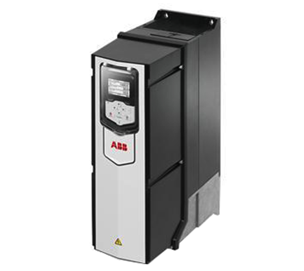
Modern inverters offer several features that enhance their performance and reliability. They are known for their high conversion efficiency, enabling them to rapidly and efficiently convert DC to AC power. In terms of safety, inverters come equipped with multiple protection mechanisms. These include protection against short circuits, overloads, over or under voltage, and overheating. Physically, inverters are typically housed in all-aluminum shells, which provide excellent heat dissipation and resistance to physical impacts, ensuring durability even in challenging environments. Additionally, inverters are highly adaptable, supporting various loads, from light household electronics to industrial machinery.
Function of the Inverter
The primary function of an inverter is to convert DC power into AC power, allowing various electrical devices to operate. This conversion involves several key components, including an inverter bridge, control logic, and a filter circuit, all of which work together to generate a stable AC output. The resulting AC power can be used to power a wide range of devices, such as computers, home theaters, televisions, refrigerators, washing machines, and even industrial tools.
Working Principle of Inverters
The working principle of a fully controlled inverter involves an inverter bridge circuit that includes Insulated Gate Bipolar Transistors (IGBTs). These IGBTs are controlled by pulse width modulation (PWM), which switches the DC current on and off in rapid cycles to create an alternating current. When the inverter is connected to a DC power source, the IGBT modules (Q11 and Q14) are turned on, while the others (Q12 and Q13) remain off. This allows the current to flow from the positive terminal of the DC source through Q11 and an inductor, passing through the primary coil of a transformer, before exiting through Q14 and returning to the negative terminal of the power source.
After Q11 and Q14 turn off, Q12 and Q13 are activated, reversing the direction of the current flow in the primary coil of the transformer. This alternating flow creates a positive and negative square wave in the transformer’s primary coil. Through high-frequency PWM control, the switching action of the IGBTs generates AC voltage in the transformer’s secondary coil. The final output, a sine wave, is formed by passing the AC voltage through an LC filter circuit, which smooths the waveform, making it suitable for use in electrical devices. The diodes (D11 and D12) ensure efficient energy use by returning stored energy from the inductor back to the DC power supply.
In a semi-controlled inverter, thyristors are used as the main switching components. The thyristors (Th1 and Th2) are triggered alternately. When Th1 is turned on, current flows through the transformer, and the commutation capacitor (C) charges to a higher voltage. Then, when Th2 is triggered, it turns off Th1, causing the current to flow in the opposite direction and charging the capacitor with reversed polarity.
The inductor (L) is employed to control the discharge current of the commutation capacitor, ensuring that the circuit shuts down properly without requiring a large capacitor. Additionally, feedback diodes (D1 and D2) help release any remaining energy in the inductor and return it to the power supply, further enhancing the efficiency of the system.
Why Choose Us
With over a decade of experience, we are experts in providing customized solutions for industrial power needs. Our inverters are designed with cutting-edge technology, ensuring high conversion efficiency, durability, and comprehensive safety protections. Backed by a one-year warranty and 24-hour online support, we guarantee reliable service and unmatched quality. Choose us for your inverter needs and experience efficient, safe, and stable power conversion solutions.


